
Vehicle Applications
GM | SUV, Sedan, & Coupe
- (2019-2025) | Non-Amplified Systems

↳ Installation Time

Introduction
These instructions will guide you through the sub kit installation for your vehicle.
TIP Before you begin, review these instructions thoroughly and ensure that all parts are present and tools are available.
WARNING Metra Electronics does not assume any responsibility for damage resulting from incorrect Installation.
↳Tools
Tools
- Phillips Driver
- Rachet
- Sockets:10mm,13mm
- Panel Removal Tool
- Unibit (Step Drill Bit)
- Wire Strippers
- Soldering Equipment
- Zipties
System Components
- Axxess AXSUB Interface
- Vehicle Specific T-Harness: LD-DSP-GM30, LD-DSP, GM31, LD-DSP-GM32, LD-DSP-GM33
- Active Noise Canceling (ANC) Bypass Harness (ANC-GMH1, ANC-GMH2)
- Raptor R5 Pro Series 4AWG Amp Kit
- 12GA Speaker Wire (LD-12GA-6)
- Vibe Powerbox 650.1 Mini Amplifier
Safety Protocols & Preliminary Vehicle Preparation
Battery Disconnection & SRS Integrity
The strategic preparation of a vehicle is not merely a preliminary step; it is the foundation upon which high-fidelity electrical integration is built. In modern automotive systems, where sensitive electronics and safety modules are interconnected, following a disciplined preparation protocol ensures both the longevity of the aftermarket hardware and the integrity of the vehicle’s factory systems. Electrical safety is the non-negotiable prerequisite for a successful installation.
WARNING ELECTRICAL & SRS SAFETY With the key removed from the ignition, use a 10mm socket to disconnect the negative battery terminal. It is critical that all airbag indicator lights remain plugged in during installation. Do not reconnect the battery if any SRS (Supplemental Restraint System) components are disconnected, as this will trigger permanent fault codes and system errors.
Adhering to these safety steps prevents accidental electrical shorts and safeguards the SRS system, providing a secure environment for subsequent technical integration.
RPO Code Identification
To select the correct Axxess AXSUB T-Harness, you must locate the vehicle’s Regular Production Option (RPO) codes. These are found on the "Service Parts Identification" sticker, typically located inside the glovebox or on the driver-side door jamb. Scan the alphabetical list for 3-digit radio codes such as IOS, IOT, IOR, IOU, or IOK.


Harness Compatibility Table
Verify your vehicle and RPO code against the table below. Each configuration maps to a specific Axxess Kit Model required for signal integration.
Make | Model | Year Range | RPO Code / Audio System | Axxess T-Harness | ANC Module RPO Code | ANC Bypass Harness |
BUICK | Envision | 2022-2023 | IOK | LD-DSP-GM32 | ||
BUICK | Envision | 2022-2023 | IOR | LD-DSP-GM33 | ||
CHEVROLET | Blazer | 2019-2023 | IOU, IOS, IOT | LD-DSP-GM30 | NKC | ANC-GMH1 |
CHEVROLET | Camaro | 2019-2023 | IOR | LD-DSP-GM31 | UQ3+NKC | ANC-GMH1 |
CHEVROLET | Camaro | 2019-2023 | IOU, IOS, IOT | LD-DSP-GM30 | UQ3+NKC | ANC-GMH1 |
CHEVROLET | Cheyenne | 2019-2021 | IOR | LD-DSP-GM31 | ||
CHEVROLET | Cheyenne | 2019-2021 | IOU, IOS, IOT | LD-DSP-GM30 | ||
CHEVROLET | Cheyenne | 2022-2024 | IOK | LD-DSP-GM32 | ||
CHEVROLET | Colorado | 2019-2022 | IOR | LD-DSP-GM31 | ||
CHEVROLET | Colorado | 2019-2022 | IOU, IOS, IOT | LD-DSP-GM30 | ||
CHEVROLET | Cruze | 2019-2022 | IOR | LD-DSP-GM31 | ||
CHEVROLET | Equinox | 2019-2023 | IOR | LD-DSP-GM31 | NKC+UZ6 | ANC-GMH1 |
CHEVROLET | Equinox | 2020 | IOR | LD-DSP-GM31 | NKC+UZ6 | ANC-GMH4 |
CHEVROLET | Equinox | 2019-2023 | IOU, IOS, IOT | LD-DSP-GM30 | ||
CHEVROLET | Malibu | 2019-2022 | IOR | LD-DSP-GM31 | NKC | ANC-GMH1 |
CHEVROLET | Malibu | 2019-2022 | IOU, IOS, IOT | LD-DSP-GM30 | ||
CHEVROLET | Sonic | 2019-2022 | IOR | LD-DSP-GM31 | ||
CHEVROLET | Spark | 2019-2022 | IOR | LD-DSP-GM31 | ||
CHEVROLET | Silverado | 2019-2021 | IOU, IOS, IOT | LD-DSP-GM30 | ||
CHEVROLET | Silverado | 2019-2026 | IOR | LD-DSP-GM31 | ||
CHEVROLET | Silverado | 2022-2026 | IOR | LD-DSP-GM33 | ||
CHEVROLET | Silverado | 2022-2026 | IOK | LD-DSP-GM32 | ||
CHEVROLET | Suburban | 2021-2024 | IOK | LD-DSP-GM32 | ||
CHEVROLET | Suburban | 2021-2024 | IOR | LD-DSP-GM33 | ||
CHEVROLET | Tahoe | 2021-2024 | IOK | LD-DSP-GM32 | ||
CHEVROLET | Tahoe | 2021-2024 | IOR | LD-DSP-GM33 | ||
CHEVROLET | Traverse | 2020-2023 | IOR | LD-DSP-GM31 | ||
CHEVROLET | Traverse | 2020-2022 | IOU, IOS, IOT | LD-DSP-GM30 | ||
GMC | Acadia | 2020-2022 | IOU, IOS, IOT | LD-DSP-GM30 | ||
GMC | Canyon | 2019-2022 | IOU, IOS, IOT | LD-DSP-GM30 | ||
GMC | Sierra | 2023-224 | IOK | LD-DSP-GM32 | ||
GMC | Sierra | 2019-2021 | IOU, IOS, IOT | LD-DSP-GM30 | ||
GMC | Terrain | 2019-2022 | IOR | LD-DSP-GM31 | NKC+UZ6 | ANC-GMH1 |
GMC | Terrain | 2020 | IOR | LD-DSP-GM31 | NKC+UZ6 | ANC-GMH4 |
GMC | Terrain | 2019-2022 | IOU, IOS, IOT | LD-DSP-GM30 | ||
GMC | Yukon | 2021-2024 | IOR | LD-DSP-GM33 | ||
GMC | Yukon | 2021-2024 | IOK | LD-DSP-GM32 |
Active Noise Cancellation (ANC) Diagnostics
Active Noise Cancellation (ANC) is designed to improve cabin acoustics by emitting counter-frequencies through factory speakers to mask engine noise. However, this system views the high-output, low-frequency output of an aftermarket subwoofer as "noise" and will attempt to cancel it, creating a significant conflict.
Evaluating RPO Codes for ANC: Verify the RPO codes on the Service Parts Identification sticker to determine if the included ANC bypass harnesses are required:
- UQ3: Standard non-amplified system (Typically does not feature ANC).
- NKC or NKC+: Active Noise Canceling is present, ANC Harness is required
- UQA / UQP: Bose Premium systems (Usually features ANC and requires the bypass).
(These RPO codes will not work with this kit.)
CAUTION ANC INTERFERENCE Failure to bypass an active ANC system results in a distinct low-frequency drone or "hum" that increases in intensity with engine RPM, even when the radio is off.
Identifying the ANC status during the diagnostic phase prevents invasive rework after the cabin has been reassembled.
Axxess AXSUB Interface Integration
The Axxess AXSUB interface serves as the system's primary signal processor. It intercepts the factory radio's output and converts it into a clean, high-voltage 5V RMS signal. This provides the aftermarket Vibe amplifier with a low-noise input, ensuring the bass remains articulate and powerful.
- Disassembly: For vehicle-specific disassembly instructions, refer to metraonline.com. Enter the vehicle's year, make, and model into the Vehicle Fit Guide for Radio Install Kits.
###

- T-Harness Connection: Seat the vehicle-specific T-Harness between the HMI (radio brain) and the factory wiring. (FIG A)
- 8-Pin Molex Requirement: The harness features an 8-pin Molex male-to-female connector. These must be connected to each other to maintain the factory speaker circuit. Failure to do so will result in a total loss of sound from factory speakers. (FIG B)
- Remote Turn-On Wire: Connect the Brown Remote Turn-On wire from the interface to the Blue Remote Wire from the amp kit. wire. (FIG C)
- Signal Routing: Route the RCAs and the extended remote wire along the passenger side floorboard. At this time, we recommend running the PB650.1D bass knob wire (FIG D) from the preferred mounting location in the dash, along with the RCA’s and remote turn-on wire, to the amplifier location.

- Door Trim Removal: Remove the trim panels from the passenger-side front and rear doors to properly route the wire bundle to the rear passenger area.
- With the dashboard electronics integrated, the focus transitions to routing the signal and remote cables through the chassis, following the factory wire looms to ensure a clean, protected path to the rear of the vehicle.
Power Wire Installation
A high-performance amplifier requires stable power. Using 4 AWG Oxygen-Free Copper (OFC) ensures the system remains stable under heavy transient loads without voltage drops that could trigger protection modes.
Power Wire Routing
Access the OE battery, usually located in the engine compartment.
- Connect the 18-inch 4 AWG power cable to the MANL fuse holder.
- Use a socket to attach the 18” 4 AWG power cable to an available battery lug.
- Connect the 17 ft 4 AWG power cable to the opposite end of the MANL fuse holder.
- CRITICAL SAFETY WARNING: Do not insert the 100-amp MANL fuse into the holder until the entire installation is complete and all wiring has been double-checked for shorts.
Chassis-to-Cabin Routing
- Path: Route the 4GA power wire down the firewall and along the frame rail. Secure the wire with zip ties, keeping it away from heat sources and moving suspension parts.
- Entry: Route the power wire into the vehicle cab through an unused grommet in the firewall. Secure the cable with zip ties, keeping it away from high-heat sources like the exhaust. Remove the grommet, cut a small access point for the wire, and reinstall.
- Use a Unibit if a new hole is required, ensuring the edge is protected.
Grounding Best Practices
- Length: Keep the 4 AWG ground cable to a maximum of 3 feet.
- Contact: Find a solid metal point on the chassis near the amplifier. Sand the area to bare steel for maximum surface conductivity.
- Prohibition: Never use seatbelt anchor points, as they are often treated or insulated, creating high-resistance points.
This secure power foundation ensures the Vibe Powerbox 650.1 operates within its designed thermal and electrical limits, preventing premature equipment failure.
Amplifier Calibration & Thermal Management
Technical Specifications
VIBE Powerbox 650.1
- Max power: 1200 W
- Power output @ 4 ohms: 325 W
- Power output @ 2 ohms: 475 W
- Power output @ 1 ohm: 650 W
- Class D
"Gain" is a process of input sensitivity matching rather than a volume control. Setting the gain incorrectly is the primary cause of hardware failure in high-performance systems.
Baseline Settings Matrix: Vibe Powerbox 650.1


Setting | Recommended Position |
REMOTE | 4-Pin cable input from Vibe Remote Bass Knob |
LPF (Low Pass Filter) | 120Hz (1 o'clock) |
Subsonic Filter | 25Hz (11 o'clock) |
Bass Boost | 0dB (Fully Counter-Clockwise) |
Gain | 12 o'clock (STRICT LIMIT) |
Input | RCA input |
MODE Switch | Slide to the LEFT for REM ON |
Do not increase the Gain dial beyond the 12 o'clock position. Exceeding this limit will cause the subwoofer to exceed its thermal capacity, resulting in permanent hardware failure.
System Programming
The AXSUB interface requires a signal-sensing handshake with the GM factory radio to synchronize data and turn-on protocols.
Programming Checklist
- Insert the 100-amp MANL fuse and reconnect the negative battery terminal.
- Turn the ignition ON. Set the radio audio volume all the way down and the Vibe remote bass knob to 1/4 volume.
- Gradually increase the radio to a normal listening level.
- Wait 15 seconds for the interface to sense the audio signal and auto-program.
- Verify that muting the radio or turning the volume to zero deactivates the amplifier.
Before permanently reassembling the vehicle trim and dashboard, perform a final inspection of all wire routing to ensure no cables are pinched or exposed to moving parts.
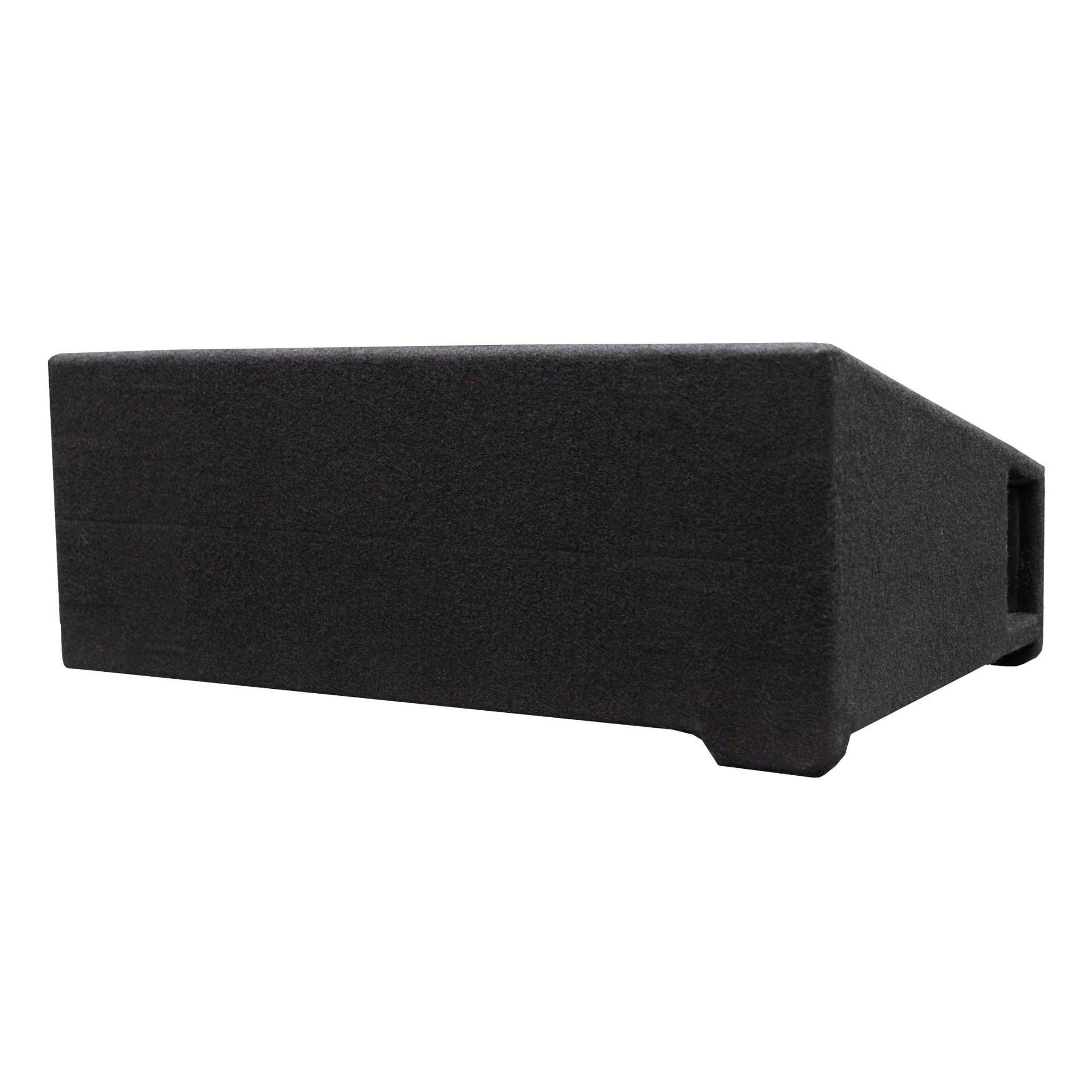
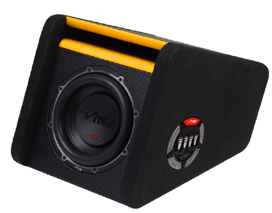
Subwoofer Options
The Vibe 650.1 is capable of handling up to a 1 Ohm load. If you are using an existing enclosure, consult the manufacturer's recommended wiring setup. If you are looking to add an enclosure, see the best paired options mentioned below.
Troubleshooting
Modern GM data-bus systems require specific diagnostic checks if the system does not behave as expected.
Symptom | Probable Cause | Solution | Verification |
No sound from factory speakers | Unconnected bypass | Verify the 8-pin Molex on the T-Harness is seated. | Audio restored to all door speakers. |
Amplifier will not power on | Signal/Remote issues | Raise the radio volume for signal sensing; check continuity of Brown/Blue/White. | Green Power LED illuminates on Amp. |
No subwoofer output (Amp On) | Signal path break | Inspect RCA connections and ensure Bass Knob is not at minimum. | Subwoofer movement and audible bass. |
Amplifier Red LED (Protection) | Electrical fault | Check the ground for bare-steel contact; verify the 4-ohm series load. | LED turns from Red to Green. |
RPM-dependent drone/hum | ANC Interference | Verify RPO codes (UQA/UQP) and install ANC bypass. | Silence from the sub when the radio is off/engine is running. |
This concludes the installation. Ensure all interior panels, trim pieces, and safety components are restored to their factory positions. Your GM-SUB-KT2 system is now fully integrated and ready for service.
Technical Support
TIP If you encounter any difficulties during installation please carefully review the instructions and ensure that the installation was performed exactly as instructed.
Our dedicated team is here to provide you with expert assistance and guidance. Whether you're troubleshooting an installation, seeking product information, or looking for technical advice, we're committed to ensuring your experience with Metra Electronics products is seamless and satisfying.
WARNING Before contacting Metra Technical Support, ensure the vehicle is in a ready state to perform troubleshooting steps.
Contact
(386) 257-1187
Hours (EST)
Monday-Friday: 9:00 am - 7:00 pm Saturday: 10:00 am - 5:00 pm Sunday: 10:00 am - 4:00 pm

On This Page
- Vehicle Applications
- GM | SUV, Sedan, & Coupe
- ↳ Installation Time
- Introduction
- ↳Tools
- Tools
- System Components
- Safety Protocols & Preliminary Vehicle Preparation
- Battery Disconnection & SRS Integrity
- RPO Code Identification
- Harness Compatibility Table
- Active Noise Cancellation (ANC) Diagnostics
- Axxess AXSUB Interface Integration
- Power Wire Installation
- Power Wire Routing
- Chassis-to-Cabin Routing
- Grounding Best Practices
- Amplifier Calibration & Thermal Management
- Technical Specifications
- System Programming
- Programming Checklist
- Subwoofer Options
- Troubleshooting
- Technical Support
- Contact
- Hours (EST)